Copyright (c) Hyperion Entertainment and contributors.
AmigaOS Manual: Workbench Preferences: Difference between revisions
| Line 280: | Line 280: | ||
The Locale editor lets you choose the languages with which you interact with the Amiga. The default setting is USA English; however, you can use the Locale editor to choose another language. See Chapter 6 for a full description of the Locale editor. |
The Locale editor lets you choose the languages with which you interact with the Amiga. The default setting is USA English; however, you can use the Locale editor to choose another language. See Chapter 6 for a full description of the Locale editor. |
||
== Notifications Editor == |
|||
The Notifications editor allows you to control the desktop notification system Ringhio. |
|||
== Overscan Editor == |
== Overscan Editor == |
||
Revision as of 15:35, 10 May 2015
This chapter explains the Preferences editors found in the Prefs drawer. These editors allow you to customize your Amiga environment by:
- Choosing a keyboard type
- Setting your preferred language
- Changing the Workbench screen display
- Changing the Workbench colors
- Changing the shape of the pointer
- Specifying a printer and setting it up for output
- Setting up a modem for use with the Amiga
- Setting the time and date
This chapter contains the following Preferences editor information:
- Contents of the Prefs drawer
- Editor menus
- Presets drawer
- Descriptions of each Preferences editor
Prefs Drawer
The Prefs drawer contains the icons for the Preferences editors and the Preset drawer. Figure 5-1 illustrates the Preferences editors window.
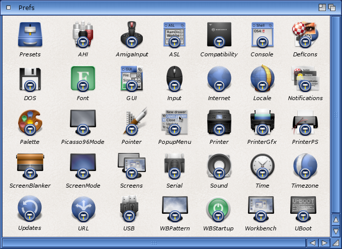
The following editors are listed in the order in which they are described in this chapter:
| Font | For changing the fonts used in the different areas of the screen. |
| IControl | For choosing miscellaneous system options, such as the key used for screen drag. |
| Input | For changing the mouse speeds, key repeat speeds, and selecting keyboard type. |
| Locale | For selecting the language and locality. |
| Notifications | For controlling the desktop notification system. |
| Overscan | For adjusting the size of the display area for text and for graphics. |
| Palette | For changing the Workbench colors. |
| Pointer | For changing the size, shape, and color of the mouse pointer and busy pointer. |
| Printer | For specifying the printer driver that matches your printer and for specifying options, such as paper size and margin width. |
| PrinterGfx | For setting up your printer to print graphics. |
| PrinterPS | For controlling output to a PostScript printer. |
| ScreenMode | For choosing a different monitor display mode. |
| Serial | For setting the specifications for the serial port, which is used to communicate through modems or networking systems. |
| Sound | For determining the sound your Amiga produces for its display beep. |
| Time | For setting the time and date. |
| WBPattern | For selecting or creating background patterns for the Workbench windows and screen. |
| Presets | For storing different Preferences editor configurations changed through the Project menu. |
Editor Menus and Presets Drawer
With the exception of Time, each editor has three menus: Project, Edit, and Settings. The Project menu lets you save and load Prefs preset files, which allow you to quickly change to different configurations. By default, these files are saved in the Presets drawer (SYS:Prefs/Presets), although they can be saved to any location you specify. If you save icons for the files (by selecting Create Icons?), you can activate the settings by opening the file's icon, rather than opening the actual editor.
When you save settings in the Preferences editors by clicking on the Save button, the system stores those settings in the following location:
SYS:Prefs/ENV-Archive/Sys/editorx.prefs
where SYS: is the name of the volume containing the file and editorx is the name of the specific Preferences editor. The settings saved to the Env-Archive drawer are the ones used when you boot. We recommend when you use the Save As option that you use the path provided or a completely different path than this for storing Preset files.
Project Menu
The following Project menu options let you save the editor settings to a specific file and open previously saved files:
| Open | Loads the information from a specified preset file. |
| Save As | Specify the preset file in which to save the currently displayed settings. The requester provides a default file name in the Presets drawer. Change this to a different name if you have more than one preset for that editor. |
| Quit | Exits the editor without performing any changes. The same as Cancel gadget. |
Edit Menu
The Edit menu options allow you to restore previously used settings or the default settings. The options are:
| Reset to Defaults | Returns the editor settings to the system default settings. |
| Last Saved | Returns the editor settings to the last settings you saved with the Save gadget (not the Save As item). |
| Restore | Returns the editor to the settings displayed when you opened the editor first. |
The WBPattern and Pointer Edit Menus have the following additional options:
| Cut | Copies and clears the whole work area to the Clipboard. |
| Copy | Copies the whole work area to the Clipboard. |
| Paste | Replaces the whole work area with the last thing cut or copied. |
| Erase | Deletes everything in the work area. |
| Undo | Undoes the last action performed. |
| Load Image | Opens a file requester for entering the name of an image file to use as a background pattern or picture. |
These options make editing patterns and pointer images easier. Use Cut, Copy, and Paste to transfer images between the editor and a Clipboard-aware program with more extensive drawing tools, such as IconEdit. Use Load Image to import any standard IFF bitmap image into the editor. (Images larger than the editor work area are cut off on the bottom and right sides when loaded or pasted.)
Settings Menu
The Settings menu contains the Create Icons? Item that allows you to save project icons for the preset files. For example, if you save printer specifications to the SYS:Prefs/Presets/Printer.pre file, an icon for the file appears in the Presets window. Double-click on the icon to activate the file's settings.
Using the Presets Drawer
Open the Presets drawer and double-click on an Presets Project icon to use its settings. Or open the editor, choose the Open menu item, and use the Load requester to select the preset. Select Use to use the settings until you reboot or open another editor file.
Font Editor
The Font editor changes fonts used on the Amiga.
For information on fonts and on using the Font Preferences editor, see Chapter 8.
IControl Editor
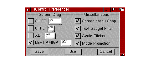
The IControl editor, illustrated in Figure 5-2, lets you change system settings, such as the screen drag qualifier key and the text gadget filter.
Screen Drag
The Screen Drag gadget specifies other keys that can be used in addition to, or in place of, the left Amiga key as the qualifier for dragging the Workbench screen. This is useful if, for example, an application uses left Amiga and the selection button for other functions.
The available keys are Shift, Ctrl, left Amiga, and Alt. To select a key, click on its check box.
If you select Ctrl, you must hold down Ctrl to drag the screen. If Ctrl and Shift are selected, you must hold down both Ctrl and Shift to drag the screen.
Screen Menu Snap
Screen Menu Snap is provided for users who work with screens that are larger than the monitor's display area. Normally the Workbench menus appear at the top left corner of the screen. If the left-most side of the screen is not visible, Screen Menu Snap shifts the Workbench screen so that the menus are still accessible. The screen shifts only while the menu button is held down.
Text Gadget Filter
The Text Gadget Filter affects whether control characters function as characters or as editing commands when entered into text gadgets. A control character is a key combination (usually Ctrl and an alphabetical key) that normally performs a certain function.
The standard control characters for text entry are:
| Ctrl+M | Same as pressing Return. |
| Ctrl+H | Deletes one character to the left of the cursor (same as Backspace). |
| Ctrl+X | Deletes the entire line. |
| Ctrl+U | Deletes all characters to the left of the cursor. |
| Ctrl+K | Deletes all characters from the cursor to the end of the line. |
| Left Arrow | Moves the cursor one character to the left. |
| Right Arrow | Moves the cursor one character to the right. |
| Ctrl+A | Moves the cursor to the beginning of the line. |
| Ctrl+Z | Moves the cursor to the end of the line. |
When Text Gadget Filter is selected, entering one of these control characters when the cursor is in a non-numeric text gadget has the function indicated above. When the filtering is off, the control character is included in the string entered; on the screen the control characters appear as an open box or other nonstandard character.
You can insert control characters into the text gadget whether filtering is turned on or not by pressing Ctrl+left Amiga along with the desired alphabetical key. For example, to enter Ctrl+M into the text gadget, press Ctrl+left Amiga+M.
| Note |
|---|
| In certain windows with several text gadgets, pressing Tab moves the cursor to the next text gadget. In these windows, even if the Text gadget filter is off, you must still press left Amiga+Tab to enter a Tab into the gadget. |
Avoid Flicker
The Avoid Flicker option prevents a back screen from becoming interlaced when the front screen is pulled down to reveal it. The default for this option is on.
Mode Promotion
The Mode Promotion gadget controls the software de-interlacing feature of Amigas with the AGA chip set. Selecting Mode Promotion allows NTSC and PAL screens opened by applications to be promoted to a non-flickering display mode. We recommend that you turn this option off when doing video work. For more information about Mode Promotion, see Chapter 7.
Input Editor
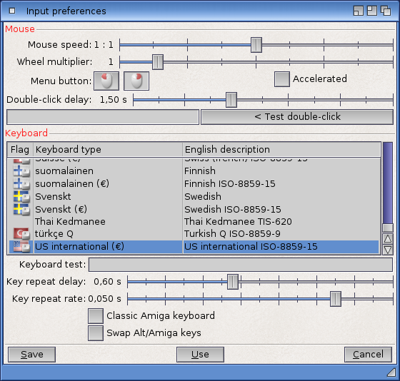
The Input editor allows you to change the speed at which the mouse and keyboard operate and to select your keyboard type. Figure 5-3 illustrates the Input-Preferences editor window.
Mouse Speed
The Mouse Speed slider determines how fast the mouse pointer moves across the screen relative to mouse movement. The faster the pointer moves across the screen, the less surface space and effort is needed to move the mouse.
Choose from three mouse pointer speeds: 1, 2, and 3, where 1 is the slowest and 3 is the fastest. Set the mouse pointer speed by dragging the slider bar until the desired value is displayed. The mouse speed takes effect while you set it, allowing you to try each speed without exiting the editor. The default value is 3.
Acceleration
The Acceleration feature is used for moving the pointer quickly over large screen areas while retaining fine control for smaller movements. If acceleration is on, the pointer speed remains constant within a small area. However, as the pointer is moved further across the screen, its speed increases, moving it quickly over a large area of the screen.
Select the check box to turn acceleration on or off. The default value is off.
Double-Click Delay
The Double-Click Delay slider determines how fast you click the selection button to register a double-click.
The range is from 1 to 200, with 1 being the least delay. The Show Double-Click gadget shows the amount of time for the selected value by displaying shading in the gadget for the length of the delay. The default value is 75, which allows approximately one second between clicks.
Test your chosen speed by double-clicking in the Test Double-Click gadget. When the double-click takes place within the allotted time, a Double-Clicked message appears next to the gadget; if not, a Too Slow message appears.
Key Repeat Delay
Most of the keys on the keyboard automatically repeat when held down. Change the delay that occurs before the key repeats with the Key Repeat Delay slider.
The current setting is shown next to the slider. The range is from 1 to 75, with 1 being the least delay. Drag the slider bar to the right to increase the delay and to the left to decrease it. The default value is 30.
Key Repeat Rate
The Key Repeat Rate slider determines the rate at which the keys repeat after the initial key repeat delay.
The range is from 1 to 125, where 1 is the slowest. Drag the slider bar to the right to increase the speed and to the left to decrease it. The default value is 100.
Keyboard Test
The Keyboard Test gadget allows you to test the settings chosen for the key repeat delay, the key repeat rate, and the keyboard type.
Select the gadget and hold down one of the alphabetic keys on the keyboard. The Keyboard Test gadget shows the character for that key in the selected keyboard type, repeating according to the current key delay and key repeat rate.
Keyboard Type
The Keyboard Type list lets you select the appropriate keyboard type for your localized system. The correct keyboard type matches the characters printed on your keyboard's keys and gives you quick access to the special characters that are part of your language and locale. If you are using a keyboard other than USA, you can use dead keys to produce accented characters. See the KeyShow description in Chapter 10 for dead key information.
| Note |
|---|
| If your keyboard type is not the default American, you must activate your appropriate keymap/keyboard. Consult your dealer if you are not sure which keymap/keyboard you should use. |
Choosing a particular keyboard type activates the corresponding keymap file in the Devs/Keymaps drawer. Select your keyboard type in the Input Preferences editor by clicking on it.
The available keymaps and the corresponding keyboards are:
| Keymap | Keyboard Type |
|---|---|
| gb | British |
| cdn | Canadien Français |
| dk | Dansk |
| d | Deutsch |
| usa2 | Dvorak |
| e | Español |
| f | Français |
| i | Italiana |
| n | Norsk |
| po | Português |
| ch2 | Schweiz |
| ch1 | Suisse |
| s | Svenskt |
If your keyboard type does not appear in the Keyboard Type list, it means that the corresponding keymap is not present in the Devs/Keymaps drawer. Install the corresponding keymap to correct this using the following steps:
- Insert either the Storage floppy disk or the disk containing the Storage drawer in any drive.
- Open the Storage window and then open the Keymaps drawer.
- Drag the correct icon into the Devs/Keymaps drawer.
Then this is complete, you can return to the Input Preferences editor to activate your keyboard type. To check your keyboard layout, use the KeyShow program in the Tools drawer. For more information about KeyShow, see Chapter 10.
Locale Editor
The Locale editor lets you choose the languages with which you interact with the Amiga. The default setting is USA English; however, you can use the Locale editor to choose another language. See Chapter 6 for a full description of the Locale editor.
Notifications Editor
The Notifications editor allows you to control the desktop notification system Ringhio.
Overscan Editor
The Overscan editor, illustrated in Figure 5-4, enlarges the size of your screen to use the extra space normally unused around the edges of the monitor screen, known as the overscan area.
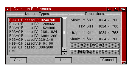
The Monitor Types available reflect the monitor drivers that are currently active. Monitor files that are in DEVS:Monitors when you boot are automatically activated. Each monitor type controls a set of display modes, called a display group.
When you change the overscan values for a particular monitor type, all modes within that type are affected. To change the overscan values for a monitor type, select its monitor type from the scrolling list. The selected group is highlighted. See Chapter 7 for listings of the maximum available overscan sizes for each display mode.
Text and Graphics Overscan
The Overscan editor allows you to set two different types of overscan: Text and Graphics. Most users can ignore the difference and set both to the same maximum value appropriate for their monitor. Having two settings can help those who use a television set as a monitor or whose monitor is unable to display a sharp image across its entire width.
The screen size and position set as Text overscan is the setting used by the Workbench screen. It can be any size between the minimum and maximum Dimensions limits, but it cannot be any larger than the Graphics overscan setting. If it is enlarged beyond the current Graphics setting, the Graphics setting is adjusted to match.
The screen size and position set as Graphics overscan are the limits within which the Text overscan area must fit and is the maximum for application screens in that display group. Graphics overscan can be any size between the minimum and maximum Dimensions limits. If the Graphics overscan area is sized or moved, the current Text overscan setting is adjusted as necessary to fit.
Using Different Text and Graphics Overscan
A television image normally extends beyond the edges of the screen itself, so that the outermost edges of the image are not visible. If some part of the Amiga's display runs off the edges of the screen on your television set or monitor or is distorted at the edges, use different Text and Graphics overscan settings.
Confine the Workbench and application screens that must remain legible to the visible area by setting Text overscan to the minimum size and centering it on the screen. The Graphics overscan area can be larger, allowing graphic images and other material for which legibility is less important to fill more of the monitor screen.
Overscan Edit Screens
Selecting either the Edit Text Size or Edit Graphics Size gadgets displays a separate screen, illustrated in Figure 5-5, on which you graphically adjust the overscan size. The Overscan editor allows you to set two different overscan regions.
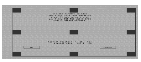
The black rectangles on the screen are handles and the line connecting the handles represents the outermost area where the Amiga's output can be displayed. Enlarge the display area by pointing to a handle, holding down the selection button, and dragging the handle to the edge of the screen. Only the active handle is visible on the screen when you drag it.
Moving any part of the handle off the screen or out of the viewing area over enlarges it, losing a portion of the visible image.
For monitor types other than NTSC and PAL, there are four arrow gadgets in the lower left area of the edit screen. The arrow gadgets allow you to shift the entire display area up, down, right, and left to center it. Move the display in the direction of the arrows by clicking on them. Depending on your monitor type, it is possible to move the display too far to the right or left, causing the monitor to go out of sync. This can result in the colors fading or a total disruption of the display. Because this condition can damage you monitor, it is important not to leave it this way for an period of time. If this happens, you can use the arrow keys on the keyboard to move the display back into position or press the Escape key, which undoes any changes you made and returns to the Overscan editor window.
Use the center handle to position the display area within the viewable area when the screen is not at maximum size. By dragging the handle, you can shift the display area in any direction to center it on your monitor screen.
The Current Position figures show the x/y distance in pixels from the upper left corner of the screen to the upper left corner of the display area. Current Size shows the size of the viewable area defined by the handles.
To accept changes and return to the Overscan editor, select OK. To exit the screen without accepting any changes and return to the Overscan editor, select Cancel or press the Escape key.
Dimensions
The different sizes of the overscan areas are displayed on the right of the Overscan window. The sizes are given in number of pixels, representing the width and the height of the screen.
For PAL or NTSC groups, the sizes correspond to the sizes for a standard High Res screen. If Multiscan is selected, the sizes for a non-interlaced Productivity screen are given. All other display modes in a group are affected proportionally.
The size categories are:
| Minimum | The standard, non-overscan size of a screen. |
| Text | The current Text Overscan size. |
| Graphics | The current Graphics Overscan size. |
| Maximum | Maximum allowable overscan size, Text or Graphics. |
Palette Editor
The Palette editor, illustrated in Figure 5-6 lets you change the colors of the Workbench.
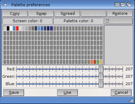
On Amigas with the AGA chip set, the left side of the Palette Preferences editor window displays either the four or eight current Workbench colors in the selection gadget, a color wheel, a gradient intensity indicator, and color sliders that can be RGB (red, green, blue) or HSB (hue, saturation, brightness) depending on your Slider Color Model menu selection. (RGB is the default setting.)
On Amigas with the ECS chip set, a gadget labeled Color Wheel... is displayed in place of the color wheel. Click on this gadget to display a screen containing the color wheel and intensity indicator. When you have made your color selection on this screen, press OK to activate it or Cancel to cancel. Pressing their gadget returns, you to the Palette Preferences editor window.
The right side of the Palette Preferences editor window has a Color Mode cycle gadget with two settings: Multicolor Settings and 4 Color Settings. The Multicolor Settings gadget is for setting eight Workbench colors. The 4 Color Settings gadget is for setting four Workbench colors. Both modes should be set to accommodate editors and applications that use one setting or the other.
The Palette Preferences editor window displays the following nine window items for which you can select specific colors:
- Background
- Text
- Important Text
- Bright Edges
- Dark Edges
- Active Window Title Bars
- Active Window Titles
- Menu Background
- Menu Text
Below the Workbench items list is a color selection gadget containing four or eight color boxes similar to the color selection gadget above the color wheel.
Depending on the display mode, width, and height set in the ScreenMode Preferences editor, the bottom of the Palette Preferences editor window can display a sample window that changes as you change color selections. This display shows the elements contained in a typical Workbench window, including a screen title bar. If the sample does not appear on your Palette Preferences editor window, a Show Sample gadget is displayed instead. Clicking in this gadget displays the sample window showing your color selections. You can click on the items in the sample to select the elements whose colors you wish to change.
You can choose the color or item you wish to change by clicking on:
- A color box within one of the two color selection gadgets.
- An item in the window elements list.
- An item on the sample window.
The following four methods can be used to change colors or their shade:
- Using the RGB mode color sliders.
- Using the HSB mode color sliders.
- Using the color wheel.
- Using the gradient slider next to the color wheel.
Changing the black and white settings can affect the three-dimensional appearance of the screen. Be sure colors replacing black are darker than colors replacing white.
To change color using the color wheel:
- Point to a color in the selection gadget above the color wheel or below the Workbench items list and click the selection button.
- Point to the color intensity indicator (the highlighted dot within the color wheel) and hold down the selection button.
- Moving the mouse pointer moves the indicator on the color wheel, changing the color in the display box and on the sample screen as the indicator moves. Release the selection button when you reach the color you want.
To change a color's shade using the gradient slider:
- Point to a color in the selection gadget above the color wheel or below the Workbench items list and click the selection button.
- Point to the highlighted bar within the gradient slider and hold down the selection button.
- Moving the mouse pointer up or down within the gadget lightens and darkens the color.
To change a color in RGB mode:
- Point to a color in the selection gadget above the color wheel or below the Workbench items list and click the selection button.
- Use the slider gadgets to change the selected color. The color in the display box and on the sample screen changes as the bar is dragged through the slider box.
To change a color in HSB mode:
- Point to a color in the selection gadget above the color wheel or below the Workbench items list and click the selection button.
- Use the slider gadgets to change the selected color. The color in the display box and on the sample screen changes as the bar is dragged through the slider box.
The Hue slider changes the basic color, the Saturation slider changes the amount of color, and the brightness slider changes the lightness or darkness of the color.
In addition to the standard Preferences menus, the Palette editor also has a Presets menu item in the Edit menu that contains predetermined color settings and a Settings menu item that lets you determine which Slider Color Model to use for changing your colors.
If you have a monochrome monitor or if you choose a color setting of 2 in the ScreenMode Preferences editor, the Palette Preferences editor only displays RGB color sliders.
Pointer Editor
The Pointer editor lets you change the color, size, and shape of the mouse pointer and the busy pointer. Figure 5-7 illustrates the Pointer editor window. A magnified view of the current pointer is shown to the left. To the right are reduced copies of the pointer, showing how it looks against the Workbench colors.
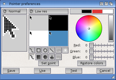
The Pointer cycle gadget above the magnified view box lets you select either the mouse pointer or the busy pointer for editing.
The pointer has three changeable colors on an unchangeable background. Areas using the background color are transparent.
To change the colors of the existing pointer:
- Select a color from the color selection gadget.
- Change the amounts of red, green, and blue in that color using the three color sliders.
To create a new pointer, you can draw it pixel by pixel:
- Select the Clear gadget to erase the contents of the magnified view box.
- Select the color with which to draw.
- Point within the magnified view to position a pixel and click the selection button. Hold the selection button down to draw with that color.
Repeat Steps 1 through 3 until your design is complete.
- Select the Set Point gadget and then click on one of the pixels in the pointer to position the pointer's hot spot.
- Click on Use to use the pointer you created in this session or Save to use it across sessions.
The Test gadget lets you change the screen pointer to see how it looks at actual size without closing the editor.
The Cancel gadget cancels all changes and closes the editor window.
The Clear gadget erases the magnified view box. All pixels change to the background color for drawing a new pointer.
The Resolution cycle gadget lets you choose between High Res and Low Res settings. This is available only on Amigas with the AGA chip set. Selecting High Res provides twice as many pixels to work with, giving you finer detail and more control over your drawing.
The Set Point gadget lets you choose where to put the pointer's point or hot spot. In the magnified view, the point pixel is surrounded by a different color. Select the Set Point gadget and click on the position where the hot spot is to be located.
The Reset Color gadget returns the last set of colors that were in use when you entered the editor.
The Project and Edit menus have the Open, Save As, Quit, Cut, Copy, Paste, Erase, Undo, Load Image, Reset to Defaults, Last Saved, and Restore items described starting on page 5-4.
Printer Editor
The Printer editor lets you specify the type of printer you are using, and the type of output you want. The Printer Preferences editor is described in detail in Chapter 9.
PrinterGfx Editor
The PrinterGfx editor supports extended printer graphics features. For example, PrinterGfx lets you determine your margins, select and correct the colors, set the dithering method, and scale your graphics. The PrinterGfx Preferences editor is described in Chapter 9.
PrinterPS Editor
The PrinterPS editor controls the features of PostScript printers. This editor only applies if you have a PostScript printer and if you choose PostScript in the Printer Preferences editor. The PrinterPS editor is described in Chapter 9.
ScreenMode Editor
The ScreenMode editor, illustrated in Figure 5-8, lets you select the display mode for the Workbench screen. Since the modes have different properties and hardware requirements, review the descriptions provided here and in Chapter 7 to determine which modes are available on your system and best meet your needs.
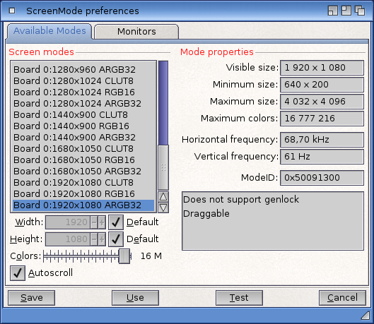
The available display modes are listed on the left; the properties of the mode selected are displayed on the right.
Using the ScreenMode Editor
The available display modes are shown in the Display Mode list. Scroll through the list to see all modes available. The available modes reflect the currently active monitor drivers. Place the associated monitor files in the Devs/Monitors drawer to have its display modes available at all times.
Select a display mode from the list by clicking on it. The selected mode is highlights. Select Save to use the mode and save it as the default in future sessions. Select Use to use the mode for the current session only. When trying different display modes, select Use rather than Save when you exit ScreenMode. When you have settled on the display mode you intend to use, save it. This makes recovery easier if you select a mode that is not compatible with you monitor. Select Cancel to exit the editor without making any changes.
If you select Save or Use while an application or Shell window is open on the Workbench screen, a requester appears, asking you to close any open windows other than drawers. When you have closed the last open Shell or application window, the Workbench screen automatically rests to the new display mode.
Your chosen display mode pertains only to the Workbench screen. Applications opening their own screens supply documentation of the display modes they support.
Mode Properties
The Mode Properties display box lists information about the display mode selected. It displays screen sizes and maximum displayable colors for the selected display mode and other mode properties.
Screen sizes corresponding to the currently selected display mode are given in pixels. The first number represents the width of the screen; the second number represents the height.
| Visible Size | The size of the visible area of the screen as determined by the Text Overscan settings. |
| Minimum Size | The smallest, or minimum, screen size supported by the selected display mode. |
| Maximum Size | The largest, or maximum, screen size supported by the selected display mode. The amount of Chip memory available can further restrict this size. |
| Maximum Colors | The maximum number of colors displayable on a screen in the selected display mode. |
The possible mode properties that can be displayed include:
| Interlaced | The display mode is interlaced. |
| Requires ECS | Only available if your Amiga has at least the Enhanced Chip Set; this is also available to systems with the AGA chip set. |
| Supports Genlock | The display mode supports the use of video genlock equipment. |
| Draggable | The display mode supports a draggable Workbench screen. A draggable screen can be pulled down to reveal any other open screens behind it. |
Width/Height
Use the Width and Height text gadgets to customize the size of your Workbench screen. Enter a number between, or equal to, the minimum and maximum width and height. Once the number is entered, that number remains constant no matter what display mode is selected until the corresponding Default gadget is selected.
Entering numbers larger than the maximum or smaller than the minimum is the same as specifying the maximum or minimum.
The Default check box to the right of each gadget lets you select the default setting for the width and/or height. This equals the Visible Size.
You can specify a Width and Height much larger than the visible size. This extra-large virtual Workbench screen lets you open larger and more non-overlapping windows than otherwise possible, limited only by available Chip memory.
Colors
The Colors slider gadget lets you select the number of colors that can be displayed on the screen. The fewer colors selected, the faster the screen can be redrawn and the less memory used.
AutoScroll
When AutoScroll is selected, the screen automatically scrolls when the mouse reaches the edge of the screen's visible portion. This is useful when you have defined a Width or Height for the screen that is larger than the visible size.
Serial Editor
The Serial editor, illustrated in Figure 5-9, sets specifications for serial communication on your system.
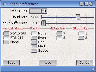
Serial information sent and received through modems or networks must be in a form compatible with the device with which you are communicating. Refer to the documentation packages that came with your serial device to determine appropriate settings.
Baud Rate
The baud rate determines the number of bits transferred through the serial port each second. In serial communication, information is sent and received one bit at a time. Since characters are usually 10 bits (1 start bit, 8 data bits, 1 stop bit), dividing the baud rate by 10 approximates how many characters per second (cps) are transmitted.
The selected baud rate must match the rate of the device with which you are communicating. The larger the value, the faster the data is transferred. The available rates are: 110, 300, 1200, 2400, 4800, 9600, 19200, and 31250 baud. The current rate setting is shown to the left of the slider. The default setting is 9600.
Input Buffer Size
The input buffer is an area of memory set aside for incoming serial data. The available sizes are: 512, 1024, 2048, 4096, 8192, 16384, 32768, and 65536 bytes. The current size is shown to the left of the slider. Use a larger buffer when working with a high baud rate or when the Amiga is performing many tasks. The default setting is 512.
Handshaking
Handshaking controls the flow of information through the serial port and the attached device. The same handshaking method must be set for both the computer and the device to allow communication. The available choices are:
| XON/XOFF | This is the most common method. Special characters called XON and XOFF are embedded in the data stream between the two devices to regulate the data flow. |
| RTS/CTS | Separate control lines called RTS (Request to Send) and CTS (Clear to Send) regulate the data flow. This method requires a properly wired serial cable. |
| None | Handshaking is shut off, allowing communication between devices without restriction or regulation. Use this option with caution. |
Parity
Parity detects transmission errors by checking a bit of each character, called the parity bit, for its setting. The available parity settings are:
| None | All bits are used for data. This should be used when Bits/Char is set to 8. No parity checking occurs. |
| Even | The total number of ON bits in each character should always be an even number. |
| Odd | The total number of ON bits in each character should always be an odd number. |
| Mark | The parity bit is always ON. |
| Space | The parity bit is always OFF. |
Bits/Char
Bits per character specifies the number of bits that are sent through the serial port for each character and the number of bits expected for each character received.
This setting should correspond with the setting for parity. If parity is set to Even, Odd, Mark, or Space, set bits per character to 7 since some systems use the eight bit of data for parity checking. If parity is set to None, set bits per character to 8.
Stop Bits
Stop bits are extra bits added at the end of a character to allow the computer to interpret spacing between words and indicate when a transmission ends. This applies to characters both sent and received through the serial port.
Slower processing computers usually require two stop bits. Computers that transfer information at 300 baud or faster generally require one stop bit. If you are using eight data bits, use only one stop bit or you may lose data during transmission.
Multiple Units
If you have additional serial ports on your system, you can specify a default unit by adding a UNIT command line option or putting a UNIT Tool Type in the program's icon. The causes a Default Unit text gadget to appear in the Serial editor window. In this gadget, enter the unit number of the port that should be used when a particular port has not been otherwise specified. Entering 0 or 1 specifies the motherboard serial port. The documentation for your serial expansion device should give the unit numbers to use for its ports. Settings made in the Serial editor affect all ports.
Sound Editor
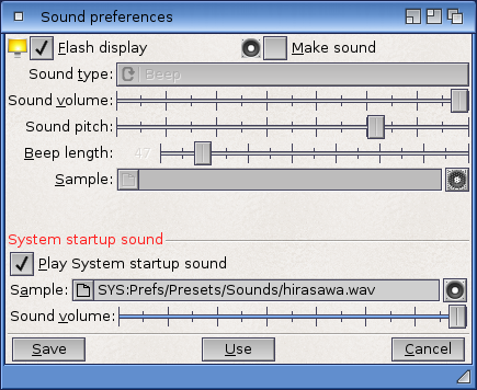
The Sound editor lets you determine the type of sound and sound attributes produced by your Amiga. The Amiga can flash the screen and/or issue a beep to signal of an application prompt or error in processing. The Sound editor window is illustrated in Figure 5-10.
| Note |
|---|
| Your Amiga or monitor must be equipped with speakers for it to make sound. Consult your hardware documentation or Amiga dealer for information on connecting speakers. |
You can choose Make Sound, Flash Display, or a combination of both. Do not turn both functions off at the same time since that disables all signaling capability, which could cause you to miss a prompt.
Choosing Flash Display alone causes the Amiga to signal a prompt or error by flashing the screen.
If you choose Make Sound, you have the following options:
| Sound Type | Select Beep or Sampled Sound. The Beep is a simple tone. The Sample Sound Type is a standard sampled sound file. You can create a sound file yourself with a sound digitizer or load from a sample sound file, for which you have a sound data type. Sampled sound files that are created for the Amiga can be purchased. |
| Sound Volume | Set Sound Volume between 1 for the quietest and 64 for the loudest. |
| Sound Pitch | Set Sound Pitch between 1 for the lowest pitch and 3000 for the highest. For a beep, Sound Pitch controls the tone pitch (high or low frequency; for sampled sounds it controls the play back speed (the number of samples played per second), which affects both the pitch of the sound and its duration. |
| Beep Length | Set Beep Length between 1 for the shortest duration to 100 for the longest duration. |
| Select Sample | Use the Select Sample gadget with t he file requester to select the file name of the sample. Sound accepts sound sample files for which you have a data type, such as 8SVX. If you save this sample setting, the sample file must be available each time you reboot, either on hard or floppy disk. |
After you choose Beep or designate your sample sound, you can test the sound to be sure it has all the attributes that you want by selecting Test Sound. The Save, Use, and Cancel gadgets do not work while the sound is being tested.
Time Editor
The Time editor lets you set the date and time on your system. Figure 5-11 illustrates the Time Preferences editor window.
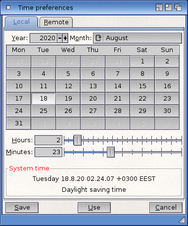
To set the date:
- Click the cycle gadget in the upper right corner until the correct month is displayed.
- Select the year text gadget, delete the incorrect year, and enter the correct year.
- Select the correct day from the calendar display. The day is highlighted when selected.
To set the time:
- Point to the slider bar in either the Minutes or Hours slider.
- Drag the bar to the right to increase the value and to the left to decrease the value. When the correct value is shown, release the selection button. Repeat these steps for the other slider.
WBPattern Editor
The WBPattern editor lets you change the background display of the screen and the Workbench and its windows. The WBPattern editor window is illustrated in Figure 5-12.
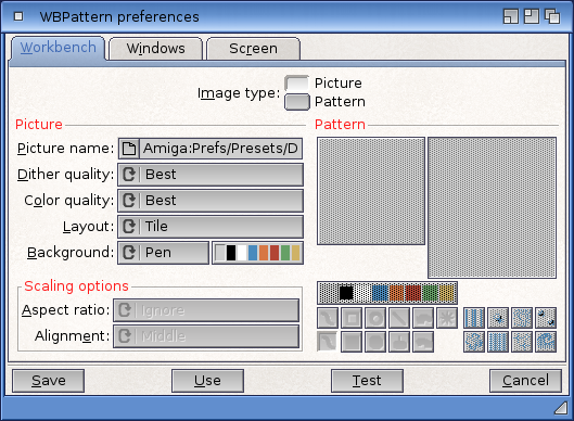
The Placement cycle gadget lets you select the following for displaying a background:
| Workbench | The Workbench window, regardless of whether Backdrop is selected. |
| Windows | Disk or drawer windows, but not the Shell or tools windows. |
| Screen | The Workbench screen when Backdrop is not selected. |
The Type cycle gadget lets you select:
| Pattern | Allows you to create a pattern or use a preset pattern to apply to the Workbench, Windows, or Screen display. |
| Picture | Lets you select a picture to apply to the Workbench, Windows, or Screen display. |
Applying Background Patterns
You can select an already existing pattern or create your own to fill any open areas for the window. The default is no pattern.
To choose a preset pattern:
- Make a selection in the Placement cycle gadget: Workbench, Windows, or Screen.
- Select Pattern from the Type cycle gadget.
- Select one of the patterns in the Presets gadget to show a sample in the display box above it.
- You can optionally select the Test gadget to apply the pattern to the screen without exiting the editor.
To create a pattern:
- Make a selection in the Placement cycle gadget: Workbench, Windows, or Screen.
- Select Pattern from the Type cycle gadget.
- If there is a pattern in the magnified view box, select the Clear gadget to fill the magnified view box with the currently selected color as a background.
- Select a color for drawing from the color selection gadget. Or select a pattern from the Presets gadget and use the mouse to edit it.
- Point within the magnified view box to where you wish to draw and click the selection button.
On pixel of the selected color appears where you position the mouse pointer. Holding down the selection button and moving the mouse fills in several pixels at once. Select and draw in other color as necessary.
As the pattern is created in the magnified view, it also appears in the actual-size box so you can see how the pattern looks tiled onto a larger area. If you make a mistake while drawing, use the Undo gadget to erase the last action performed by the mouse. - When the pattern is completed, select the Test gadget to see how it appears on the screen.
Applying Pictures
You can apply a picture or graphic file to the background of the Workbench, Windows, or Screen. Pictures can be created in a paint package or you can load digitized picture files into the editor. Pictures are mapped to the colors of the screen.
To select an existing picture file:
- Select Picture from the Type cycle gadget.
- Click on the Select Picture gadget.
- In the file requester, enter the file name of the picture you wish to use.
- Optionally select the Test gadget to apply the picture to the screen without exiting the editor.
WBPattern Edit Menu
The WBPattern Edit menu has items that let you use other drawing programs to create and edit patterns and to use existing images from other sources. For example, you can use the drawing capabilities of the IconEdit tool, described in Chapter 10, to create a design and then load it into WBPattern.
| Cut | Copies the contents of the magnified view to the Clipboard and clears the view to the background color. |
| Copy | Copies to the Clipboard without clearing the view. |
| Paste | Copies an IFF image from the Clipboard to the magnified view, replacing whatever is currently there. (Images larger than the 16 x 16 pixel view are cut off on the bottom and right sides.) |
| Erase | Clears the magnified view to the background color. |
| Undo | Operates the same as the Undo gadget, exchanging the contents of the Undo and magnified views. |
| Load Image | Opens a file requester for entering the name of an image file to use as a background pattern. |
| Reset to Defaults | Resets WBPattern to default settings (no patterns). |
| Last Saved | Returns the last saved settings. |
| Restore | Restores the settings in effect when the editor was opened. |
When you Save or Use, all selected patterns or pictures are saved and/or applied where designated. Selecting Cancel also cancels any patterns or pictures applied with Test gadget.
Workbench Editor
This preference editor controls some basic parameters for the Workbench:
The list of hidden devices in the left of the window shows all physical devices on your computer (i.e. hard drive partitions, CD-ROM drives, etc.). If the checkmark to the left of a device name is active, that device will not be displayed on the Workbench screen but will remain available from the CLI, through file requesters, etc. This option is useful for e.g. hiding drives that only contain temporary data and need not be accessed from the workbench.
In the Icons section the following options are available:
| No color icons | Activating this option causes NewIcons and the new OS3.5 icons to be ignored and the 4-color icons of OS3.1 and earlier versions to be used. |
| No NewIcons | Activating this option causes all NewIcon data an icon file might contain to be ignored, using the normal" icon image instead. |
| Quality | This popup-menu controls the color allocation for icon images. The higher the quality level you select, the better the icons will look on the monitor. Please bear in mind that at the same time less colors are available for other applications to use. |
| Border size | This popup-menu provides global control over the border size used for icons and whether icons should have a border at all. Please bear in mind that it is possible to create icons that are displayed borderless, even if the global borders are enabled. |
| Stack size | This gadget controls the default stack size to use for programs that were started from workbench although they do not possess an icon. |